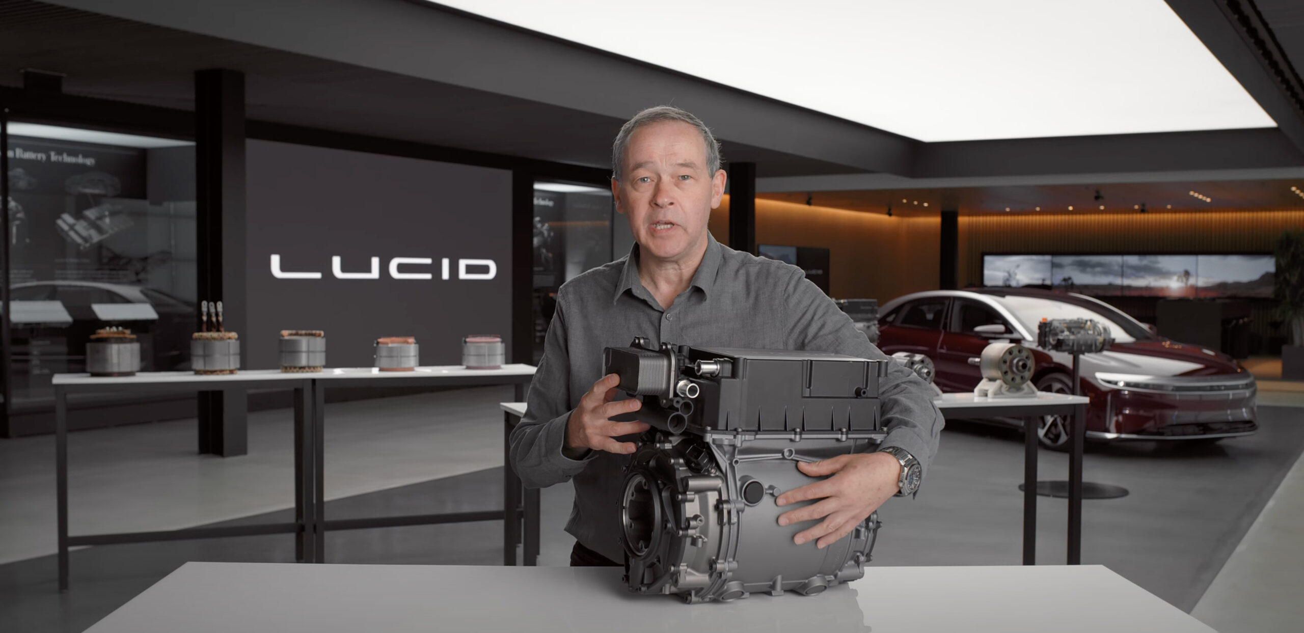
Lucid Motors has published an hour-plus-long video talking about the ins and outs of its drive unit and motor. The Lucid Air drive unit only weighs 67 pounds but is capable of 670 horsepower, which is 10 horsepower per pound, as Peter Rawlingson explained in the video.
In this video, you will see the CEO/CTO Peter Rawlinson and VP of Powertrain Emad Dlala. Here is the video:
Here is the raw transcript, if you want to try to read through it:
Hi everyone peter here from lucid motors again out with another tech talk and today there’s a palpable sense of excitement here because this is the tech talk that i know so many of you have been long waiting for because we’re going to go deep into the heart of our lucid integrated drive unit here right to its very core and explore the inner workings of the lucid electric motor a motor which just weighs around 67 pounds and yet is capable of generating 670 horsepower yes about 10 horsepower per pound and yet blends that with extraordinary unparalleled efficiency how was this even possible we’re going to delve right into the technology of that motor how it was conceived how it was analyzed how it was developed and what makes it so very special we’re going to take you through that journey and then i’m going to introduce the concept this crazy concept of the zero mass drive unit is that a fantasy is it something that might happen in the future or the craziest notion of all is it even here in production today [Music] [Music] so before we get deep into the motor let’s take a look at this integrated drive unit the lucid drive unit it comprises four discrete elements inverter here with a motor section beneath reduction gear sets and differential those are the four elements collectively this comprises 74 kilos but the motor itself is around 31 kilos just over 67 pounds now to really enhance one’s understanding of the performance of this motor i want to cover just one or two key principles starting with what’s the difference and relationship between torque and power so armed with a great torque wrench let’s explore torque so here we are with the torque wrench let’s apply a torque to this wheel nut on a lucid air and what am i doing i’m pushing down here with my right hand supporting with my left i’m applying a force multiplied by a distance force times distance that defines what torque is and we can measure that a couple of ways we can measure it with pounds feet or by newton meters and here’s an interesting little relationship uh one newton meter equals 0.7376 pounds feet and a good way of remembering that is just to think of a 737 aircraft it’s pretty close now that 0.7376 is also tantalizingly close to 0.75 so a simple way of of doing the math in your head is to think of a newton meter as about three quarters of a pound four so very close to that and conversely a pound foot is about one and a third newton meters but they’re all just measurements of simple talk force times distance now i hear some of you saying ah but if we’re going to use this to demonstrate the torque from an electric motor surely that’s going to apply to the center here of the wheel well strangely mathematically it doesn’t matter you can apply a torque and it’s to an independent position within the free body of the wheel it doesn’t actually matter in terms of where the interface forces uh how they resolve out and in this case we have the forces at the tire contact patch and the bolted connection to the hub and the brake disc so now armed with that information that torque is just force times distance let’s develop that into relationship with power in the context of an electric motor so we’ve learned that torque is just a force times a distance and we can just write this down torque equals a force that will be in newtons times a distance and that will be in meters distance x and that’s all it is i’ll just make that simpler t talk equals fx now here’s a crazy observation that the units for torque force times distance those who may have seen my previous tech talk and batteries will recognize force times the distance is something else it’s actually energy so how can torque be the same units as energy there’s a crazy construct here because there’s no movement in that talk and there’s no energy taking place because there’s no displacement but force times distance is energy and you may remember me lifting the apple which weighs about one newton about a tenth of a kilo and if i lift that exactly one meter up that’s force times distance that’s one joule and so this leads to this core construct that we can have an energy equivalence of a torque let me explain that with another little prop that i’ve got so here we have a representation of how a talk could be applied to a disc imagine the torque being applied this way and the force is being applied at the outside of the disc here and it’s been applied across this distance this distance x which is shown by this piece of string right so that’s torque force times distance but we’ve also seen that force times distance is energy so what if we consider this a completely different way what if we applied a force around the edge of this circumference through this same distance through this piece of string the force then would go along this arc and it would start at a point here and it would end up at a point here and the force would travel all this way that force times that distance x and when we get to this point here we see an angle has been subtended and this angle we’re going to call theta and we define that by a radian so a force times a radian is a unit of energy and we know that energy divided by time is power so if we can do this force through this distance in a set amount of time that will define power and we have a great analogy here because we know that in a linear sense power equals energy divided by time and that’s in a straight line and from this we can derive that rotational power this is this is straight line power this is rotational power equals torque times angular velocity which we will show as theta dot that effectively the energy equivalence linking power with torque through the angular velocity in radians now there’s a great similarity and synergy here between the relationship between power and energy and from that we derive that power in a straight line is force times velocity and these are key key relationships in a linear relationship power is force times velocity and in a rotational context power is torque times angular velocity in radians per second so wait a minute i hear some of you cry foul here who measures our rotational speeds in radians per second only engineers we really all talk about reds per minute so how do we get revs per minute into this formula that’s crucial now we can do that very easily because if we think of one radian per second that one complete revolution going all the way around there is actually two pi radians pi is just over three three point one four so two pi is just over six so it would take us six seconds to go one rev if we’re doing just one radian per second and that six seconds is one tenth of a minute so one radian per second is very close to not quite i think it’s about 9.56 rpm but it’s very close for doing simple uh mental arithmetic to about 10 rpm and then we can do some really fascinating math here just imagine uh if you’ve got a a motor that’s capable of all thumping 500 newton meters and imagine if that could create that torque at a crazy 10 000 rpm well actually armed with this new information that 10 rpm is about 1 radian per second we can say the power equals the 500 which is the torque times 10 000. divided by ten well those tens cancel each other out the triple naught that’s a thousand that could be a kill so the power in this case is 500 kilowatts the math is so simple that’s about 670 horsepower just do mental arithmetic divide thousands of rpms by 10 and you can instantly compute in mental arithmetic newton meters into power in terms of kilowatts now let’s develop that theory to the next level so now remember the power equals torque times angular velocity effectively times rpm what if we plotted this out on a graph what would that show us we can plot torque on this axis here and angular velocity or rpm on this axis because power equals torque times revs what would an equal power line look like on this graph it would look like a contour map of a mountain so let’s take a point uh to start with that amount of torque and that number of revs so if we double the number of breaths which would bring us out to about here we would half the torque wouldn’t we so we’d have a point around there conversely if we half the number of revs we’ll get to a point about here we double the torque and get to a point like that and so on so forth and this way we can generate a curve which is a curve of constant power on this torque versus revs graph and so on so forth that can go right up there and we can extrapolate this line right out there that’s a line of constant power an iso power line now what if we were using this in the context of designing an electric motor what if we were limited by the fundamental ability of the motor to generate a maximum torque well that would mean there would be a natural cutoff line determined by the maximum torque and what if we had a natural physical limit of the ability of that motor to spin because remember we’re going to have centrifugal forces and those are a function of revs squared so they take off exponentially double the revs you quadruple the forces the propensity of that motor to explode and so then you could create a cut off line here where that would be your maximum number of revs and as a consequence what we get is this classic shape here we get this classic envelope that defines electric motors the electric motor performance envelope and this is the operational area that the motor is capable of operating in this line defines maximum torque from the physical properties of the motor this defines the maximum power available and that’s in electric car it’s a function of many things often battery limited actually and this is the limit of the motor’s ability to spin now there’s another thing that goes on here altogether and that is the efficiency and we can create a contour map of different levels of efficiency within that envelope and overlay that and that’s even more important so what are we looking for in an electric motor what are the key attributes that we need to chase down in designing from scratch a lucid electric motor well of course we’d like to have great power but you can always have more power if you increase the size of the thing we want great power density volumetric power density because we need the space concept to work we need to shrink wrap the size and shape of the motors we want to push this power out to another line of constant power out here or even more these are lines isopower lines you know this is p1 p2 p3 we want to move that envelope out in that direction what else do we want to do well those who know a little bit about electric motors tend to be over obsessed with with talk and i’ve actually rather controversially and playfully stated i’m not so interested in the maximum talk of an electric motor why is that well what matters is the torque applied to the wheels of the car not the torque generated by the motor itself and to that aim i can use a gear ratio a transmission to adjust the torque available at the wheels by multiplying the ratio by a factor of two i can move that that maximum torque i can double it so the gear ratio would mean that this operational envelope in orange would come right up to here to a torque which is double but that comes at a price and because the gear box has a little bit of inefficiency so we’re always going to lose a bit of power so this is going to be a little bit less power but if we double the torque with a two to one ratio we’ll actually halve the actual maximum velocity the angular velocity of the system so we’ll create this orange envelope which represents the torque and angular velocity envelope at the wheel with a two to one gear ratio you see that we can have infinite control of torque available at the wheel independent of the torque available generated at the motor but it’s always at the price of the velocity we can actually in theory we never do this but you could overdrive a motor overdrive is often used with gasoline transmission systems if we were to overdrive this system conversely in theory we could create an operational envelope two to one of talk available at the wheel and that would look like that green line just just theoretically but the point is what really matters here is not talk alone it’s the bandwidth and stretch between torque available at the motor and its ability to spin the high end spin speed of this operational envelope that stretch that very bandwidth which is absolutely key it’s the combination of torque and ability to spin we want to push that torque limit up at the same time pushing that rev limit out that is absolutely fundamental not torque in its own right but that stretch that bandwidth that is key attribute of an electric motor and then finally i get back to this this contour map here of efficiencies and it’s not just the absolute value of efficiency here because a lot of the traditional electric motors are pretty damned efficiency how are we going to really make a a big stride forward on motor efficiency it’s not just the numbers but it’s the area of high efficiency values that we get in the high 90s here around this point dropping off but then we can use the transmission system to further enhance that so we actually use this a highly efficient zone of operation of the motor to best effect through the duty cycle of the vehicle in operation so it was one thing to have all these great ideas the understanding of the core principles a vision to make a more advanced more efficient more power dense electric motor than ever before unfortunately it was quite another to find the expertise to actually undertake this to make this a a material reality and many years ago when we were still a tiva i had the the the pleasure of meeting this gentleman dr ima dalala uh vice president of powertrain here emad yeah do you recall when we i recorded our first meeting by this diagram this is how i connect yes exactly exactly it was an interview question of course and you had always the vision of uh improving and extending the envelope yes of the motor through wraps and and torque and power as a system and how we improve power density and efficiency was the mission exactly so the two core tenets of undertaking this mission emad were one using really deep computer simulation going back to the laws of physics in your analysis electromagnetism thermodynamics all of that and more and then the other thing was taking a big picture view system holistic system level for example looking at the motor and transmission holistically as a single inertial rotational system absolutely peter and frankly that what actually made the difference is that system view because looking at a component at a solo you can design the best motor for what it has to be for the system exactly this is the fun part now we’re going to get down to the nitty-gritty this is the stator of the motor this is the main housing and as its name suggests it doesn’t move it’s static yeah it’s a stationary it is typically connected to a housing and then to the chassis of the vehicle and that’s why it’s called stator okay now the main role of this is to create a rotating electromagnetic field correct yeah so the idea of course to have two interactive parts stator and rotary the rotor goes through here yes yeah the stator would be the one responsible for that magnetic field rotation which would rotate the rotor with it so this is the intelligent part of the system where you’ve got the field going around and the speed that that rotates determining the speed that the motor spins and how fast the car all the intelligence related to the control the of the torque and the speed is done through the stator however the rotor plays a huge role in the torque oh of course yes exactly now we’ve got a real consistent feature here through here we have all these slots with these copper wires running through how many slots have we got here excellent so we have here one set of the lamination to show how it’s made yeah so we’ve got like a a couple of hundred of them this is about 440 kilometers as much as that they’re a quarter 0.25 millimeters right right so we we stack all these up and you can see the slots here absolutely so these are the slots are made of 72 slots don’t look at the small slots we’ll come back to that so those are the large ones are the basically the copper so the copper runs through here we’ve got one here yeah we actually let me look at this one here there we are look you see the slots with the copper so you have this aesthetic and we have this what we call a cover right now coil this copper coil is is to construct a pair of balls so you have a south and north pole so you have a current flowing flowing from one direction and goes to the other direction and this is a six pole motor so this is six poles that’s why you see three whole pairs and of course you know a multiple of 6 becomes 72 yeah so if you think about it 72 slots divided by 6 and divided by 3 is actually 4 which means that each phase is actually distributed enforcement three phases so so that’s a part of the how we smooth the torque and the air gap to generate a more uh refined torque now what we’ve done what you’ve done here something very special the way you fill those slots with the copper show me the traditional way and and and what’s different about this yeah so yeah so there there are multiple approaches so the traditional way peter to do it is to create a slot kind of round shape and now we’re going to fill it with the filamentary small stranded wires round voice round wires all around here and this is the way things have been done for the last hundred years a hundred years and today it’s still used the reasons why it’s common because it can be handmade yes and it started manually back then how to do it because it’s it’s random there’s no machining involved you can do it at home so they go in all higgledy-piggledy with lots of space yeah yeah so those wires though they are insulated yeah they are insulated remember they need to be installed yeah like there is and they’re all running through these slots generating that magnetic field to create the force and it which rotates but there are many configurations so what’s the breakthrough that you’ve done okay so what we thought about this uh when we looked into the round wire it is it has an advantage of skin effect the battery talk you spoke about power loss which is i square r indeed we came to the conclusion that resistance of the wires with their cables plays a huge role in the heat loss totally and we want to minimize we want to minimize this that’s central to that’s the center center to efficiency to improving uh the overall performance of the of of the motor now yeah great so traditionally these type of wires create low skin effect skin effect is a negative phenomena it basically it allows the current to be when it’s high the current tends to flow only in the surface this depends on the frequency of the current high frequency so the electrons want to go around the edge exactly not the center and it’s a very weird effect yeah at low frequency at dc let’s say direct current that effect is completely zero like nothing yeah they’re the current do you have higher frequencies we have to have as we go with this the skin effect does affect yeah so you remember yeah we have the resistance it goes almost quadratically so this is r yes and this is vehicle speed yes so if we have a system that can reduce that resistance from the start and it doesn’t increase at the end and this increase in resistance with velocity is a consequence of the skin effects correct frequency related effect absolutely right so what the r is getting higher and higher due to skin effect due to higher frequency at higher velocities and therefore the i squared r is proportionately larger which determines the power losses current heat and that what brings me to the other type of technology which is xiaomi yeah so if we if we make a slot with a rectangular shape yes there it is this is the one it’s identical to what we have yes one approach is to fill this completely with one single copper bar however it’s going to have a hundred percent area utilization compared with that correct but skin effects the skin effect because you’re it you have you can’t utilize this middle there’s so much skin it’s got so much you know you know so much skin effect so you’ve got a lot of copper area which is good yeah but you’ve got very little copper skin which is a bad thing if you open it at one mile per hour all the time this is the perfect yeah but once you go to higher speed frequencies that’s this would be very low dcr but it goes like this yes of course it goes so high so if you are at 50 miles per hour or higher it’s got a higher ratio of cross-sectional area to surface area correct so what we need to do is come up with a way how to basically section this into small conductors yes yes at lucid we want much a smaller conductor than conventional but the penalty for that when you go to smaller conductors how you’re going to connect them together you end up with a huge number of wheels because typically that these are made of small hairpin wires oh these are the way they come through exactly you have to laser weld them on the end exactly to make the circuit continuously so you need to strip them break those up join them yes weld them and then insulate them yeah a lot of costs absolutely the yield is very low and resistance in the welds and the resistance yes and the reliability so what you’ve achieved here is that you’ve maximized the slot fill with maximum area but you’ve also managed to introduce quite a significant extra circumference which will actually reduce the skin effects you’re getting part of the advantages of that which would help at high frequency but in order to do that with a conventional hairpin system you’d have lots of extra laser welds so what solution did you implement new technology called continuous with white this is it all these separate turbines can be replaced by a single winding made with a single chop so this becomes that let me see that and this is like a a it’s made in a loom it’s almost like a weaving process and this is continuous wave winding and i happen to know this is a revolutionary process and to the best of my knowledge the only machine that does this is in the heart of our correctory in arizona making the motors for lucid air and this is all cnc control as all cnc contract fully automated even the this all fully automated but email this is fantastic but it doesn’t quite look like that what’s the next step let me pass you the next exhibit yeah so so basically after it’s formed yes pressed and then rolled like that you insert it inside the station so this flat thing becomes that you pick up yeah and then we insert it into the car so this is inserted into that insert it then expand out expand out and then form it to make the winding even with the 72 slots correct this is a mandrel yeah and this is exactly that winding before it’s that big exactly becomes that so we’ve got this continuous wave of material correct we’ve got incredible slot fill to get the minimum resistance because you’ve got the maximum surface area of copper you’ve got multi-piece how many how many of these elements per slot so we have eight conductors as far as i know also we are the first one in production with eight conductors per slot and so you’ve got no hairpin wells that you would normally see with a square element but you still have these 24 laser wells here eight times three for the three phases connection to the inverter and we’re going to look at some other examples aren’t we yeah very soon and we’re going to see the difference because actually the competitor competition out there has a lot more wells but the key here is that heat generation is the enemy of efficiency so the first step is to reduce the heat generation at its very core but the other thing is what we still have to extract some heat because even with this system yeah so the closer to the source of heat generation that we can extract that heat the better what we don’t want is for the whole system to saturate through so here it’s this copper that generates the heat so the worst thing we could possibly do is extract the heat from this outer surface because this entire lamination stack of magnetic steel for the for the stator would get heat saturated and we only start extracting the heat there we’d have a temperature gradient between the extraction point and the copper so the cup is going to get hotter and it would have higher resistance conventionally the stators are like water cooled at the surface exactly but that’s really further from the copper wire because the copper wise has insulation it has a insulation class that goes to 100 degrees for example celsius so what was your solution our solution is to in bring the the heat extraction very close to the copper and here we have it yeah in these laminations you can see the tiny slots yeah the tiny slots the small slots here between two neighborings are copper slots and you see those micro channels we run atf which is automatic transmission fluids to extract heat from very close to the proximity of the heat and this is an incredible breakthrough that you pioneered emad because this allows the extraction of heat really close to where the cover is and how we’ve been able to do that doesn’t this interrupt the the magnetic field we we’re able to design these maker channels in a way that the magnetic field is unidirectional so it doesn’t interact and the nice thing about a trapezoidal shape the magnetic field is coming in the area here we optimize that to be exactly the same so the flux is coming through here absolutely and effectively you’ve identified this magnetic dead zone yes this is the challenge we’re using as a micro channel this is the breakthrough to get minimum heat generated to start with in the copper winding and to extract what heat is generated super close where everybody else is extracting heat around a circumference and you can see here the middle side of the of the core look different yes now you see this slop that runs around the center of the uh stator this here is a manifold and this is where the the cooling fluid is pumped against the system it just reminds me mad just again why is it made from a series of laminations why isn’t this a big block of steel why is it yeah illuminations we spoke about skin effect earlier and eddy currents briefly eddy currents it’s the eddy currents you want the magnetic flux to run round this way and you want to separate the circle this way you’re ensuring that there aren’t um actual components of eddy currents from the right hand rule we’ve got the the the we’ve got the the field we’ve got the force we’ve got the current and it’s got to go this way around so the force is driving that road around the current is going down actually down the slot and the field has got to go purely in each of these laminations absolutely so the field goes around in the laminations but we want to prevent currents flowing from one lamination to the other right now we go to a thinner and thinner laminations as we progress and i know there’s a special secret here because right at the end of these copper windings we actually reduce the size of the slots the effect of like when you’re watering your plants with your garden hose putting your finger on the end of the garden hose to get that sprayer jet effect cooling onto the end windings so this is a real interesting fusion of advances in electromagnetism and advances in thermodynamics and really to sum up i’d like to say remember that this this magnetic field actually rotates around and that’s what drives the rotor around which we’re going to look at next but what is not really understood is you know when you put your foot down on the accelerator of an electric car what that really goes on well the inverter gets that signal from your foot from the pedal and that tells the motor to spool up send signals to increase the speed by which that magnetic field rotates but it’s more complicated than that because you need to draw more current in order to accelerate it at the same time yeah and this brings me peter to an interesting point that i think is typically misunderstood so let’s just draw torque speed curve the envelope that uh yeah this is the say torque this is torque and this is a speed right yeah it could be a rotor or vehicle yes indeed um and as you know battery of the motor mechanical output of the motor zero at zero speed exactly this is a common misconception yeah because i often hear you know motor power is maximum instant at zero rpm no at zero speed power is zero torque is maximum absolutely and that’s why we tear in our of our systems at let’s say in stop lights and because power zero at the wheel even if you’re generating tor or generating uh force it’s still zero no matter what and with zero movement you’d have zero efficiency in that case yes because your output power is zero you got divided by input power which is you consume to generate let’s say magnetic fields efficiencies zero so the test case thermally for the motor is at this low speed high speed but the test case firmly for the battery is at the high speed absolutely correct and that’s why when we design our motor cooling we have to consider that not only the high power region it’s also the low power high torque acceleration particularly the low power particularly yeah so emed this is fascinating yeah i think it’s time for us to look at some examples of how some other manufacturers approach their state of design yeah let’s still well let’s start at this end this looks a familiar friend yeah this is our stator production in the lucid air today yes this is what we produce for all variants and just to summarize we see this classic wave wound wiring system no laser welds on the back just laser welds here and nothing here except for the terminals exactly and let’s go through in a little bit more detail because this is a cutaway of ours yeah we spoke earlier about the rectangular wire stacking it basically maximizes copper slot fill and you can see eight conductors as far as i know we are the first in production with eight conductor space flights almost 100 slot fill minimize resistance eight elements to minimize skin effects absolutely and we’ve got the close proximity of the micro jets there yeah so we get super close cooling and we get the necking of the jet to create a spray effect on these copper windings and crucially these are our bus bars yeah yeah fit on here yeah these bus bars this is how long this is the connection directly to the inverter so they’re about 40 mil long and remember the shorter you can make this the more efficiency you have the aim measure of design elegance and design engineering capability is the shorter you can make that it’s almost the shorter you can make them the better you are as an engineer and applying this mentality in every detail absolutely every detail yeah right what have we got here emad this is the american company this is their latest technology stator it’s in some production with their mass production yeah and mass production currently in all variants they’re very different looking yeah so this is a round wire it’s it’s a traditional way to make winding for many years random one random wire windings stranded we spoke earlier about its advantages and disadvantages and this is just like your your diagram that you drew yeah yeah it’s very similar the slot a little bit round shape to optimize more slot fill however you can always end up with a much less copper slot fill usually about 20 percent less than than that that covers that yeah but you get a little bit better skin effect yeah yeah now you’ve got what this looks like string which is tied to all these very laborious type of lacing to get the winding together and i’m just thinking about tolerancing and consistency of product yeah so there’s forming fixtures today to form the winding in such shape but yes the end winding height is definitely larger especially in the bottom side you can see it’s about 40 millimeters exactly and it’s literally tied with string compared with ours this is robotically formed totally cnc robotically created and this is exactly what we’re building today in our factory in arizona and it’s not just the quality it’s the consistency of the product which is crucial now the other thing i’m noticing here is these channels presumably for cooling right on the outside edge yeah so the heat is generated at the copper here it has to travel all the way to the outside saturate this entire mass this thermal mass compared with our smaller heat generation because we’ve got 100 slot fill and we’ve got close proximity cooling yeah much less temperature gradient but i also noticed there is a similar feature here that this manifold for the cooling is in the same place in the center of the stack but of course the direction is very different from that manifold the same idea to feed the fluid from the middle each way so it’s symmetrical it’s symmetrical but here at the from the manifold the jet the the fluid goes right into it it doesn’t stay on the surface like this so this is a step change and it’s a huge change and of course it’s all patented in-house here totally totally yeah and what we’ve got here another example of the same yeah this is it’s just uh without the cut the cut away just to show you the the terminals now that’s fascinating look at the length here yeah it’s much you know here it is yeah it’s four centimeters 40 millimeter here it’s maybe four times bigger or so is that because the length here is the enemy of efficiency you know we we as design engineers strive for the elegance yes every detail matters we want to uh reduce the losses and the heat from every portion and this is of course a significant also a heat source i i’ve seen i’ve seen a lot worse than that yeah this is actually quite good compared to seen them that long that’s correct and and i think this is the shortest flight ever this is a good integration you know i drove the whole team nuts getting this short do you remember that i remember that absolutely they were that long and we’re thankful for it it’s like every last millimeter so right so we’ve done the american but i should say also is this the same motor that we find on the fabled uh tri-motor version of that this is yeah this is absolutely this one coming from the tri-motor oh this is the one variant so that is the very latest up-to-date technology in the world right now what do we got here yeah uh gut here is a german sports manufacturer super sport and uh with a fable racing yeah so if we look on this side here we see that cnc formed very similar sort of shape to ours but it’s not continuous these are the hairpins slotted in yes and what do we got here on the top then we got them stripped yes welded and insulated so let me get my arithmetic right we’ve got 72 slots yeah and we’ve got four elements per slot so you’ve got four times 72 wells is that 288. so you’ve got all these extra and then you’ve got this thermal material here which is going to hold the heat in yeah it’s insulating material mainly for dielectric properties but because it adds this layer of insulation it also increases the thermal resistance which reduces the heat transfer right so now what about cooling because i’m not seeing any channels no channels here how is this cooled they you know they used a different approach more very more traditional approach which is called cool cooling jacket basically this is cool this is the housing of this motor so this goes over this slot so it goes right over it right over it and here we have like a spiral here yeah which has a water flow around that spiral so in this the heat is generated to the copper it has to go all the way through the lamination stack and then it still doesn’t get to the cooling fluid just to then go through this remember usually this contact between the aluminum and and and the stick can be poor it can be possible because it’s a very big surface area to get um their family tolerance correct so look uh i think that’s a fascinating overview but the proof of the pudding is in the performance yeah so let’s weigh these and see how they stack up shall we absolutely let’s just do it right so email i have the scale ready yeah let’s do it so we start with german the german super sport car and this is the stator how much is that yes so that’s 23.05 so basically 23 kilograms 23 kilograms okay yeah put it this back and go to the next we have the the american yeah and this is slightly 23.85 kilos it’s a little bit heavier than the german yeah yeah slightly almost the same maybe maybe the bus bars maybe finally the lucid motor the lucid motor and here 19.05 19. okay look so some useful data points but before we look at power to weight ratios this is only part of the story it’s only half the story yes we need to look at the full motion yeah so really that takes us to the the rotor yeah rotor we’re going to explain some theory and then we’ll come back to that let’s do that yeah great so emad we’ve gone through the stator very thoroughly we haven’t got to the part that moves yet yeah tell us about the rotor yeah so the rotor of course integral part of the of the motor it’s it is with a stator together acting at the air gap level generating torque and the rotor has a set of poles yes that magnetically interact with the electromagnets here in the state yes and this is six poles in this case it’s the sixth pose in the rotor and six poles on the stator and believe it or not the poles of the stator and rotor they don’t have to be equal but they are usually really really yeah so this is a six-pole permanent magnet synchronous motor correct and that fits just directly in that you wanna yeah so we we can show you how we can actually there we have yeah and a very narrow air gap between the two it’s usually their gap range is between point four to point eight millimeter depending on tolerances and mechanical and that’s crucial because the generator is at all it’s actually crucial to have it small yes but there is a moderate level where it can be too small for harmonics to be affecting the actually the rotary indeed so i i’m noticing a a remarkable feature here the the the rotor itself is hollow and i remember uh in the early days when we were conceiving this mode to me asking you you know what what does the middle of a rotor do something that transmits torque doesn’t that metal do virtually nothing in the middle there yeah you know we have six balls so we have a rotor with this v shape and if you think about it is the v3 for the magnets yeah so if you look at this shape here yes so we have the six poles yes yeah and the magnetic field tends to be that’s right at 90 degrees and the middle here there is not much magnetic flux going through indeed so we optimize it to remove as much steel in the middle yes and make it as a hollow shaft because the reduction but indeed if there was much magnetic flux at that reduced radius it wouldn’t have much effect upon torque absolutely now i’ve got a great analogy here emed a great classic example we’ve prepared this prop shaft from a truck and this is something that is designed to transmit torque right and we’ve cut it down the middle and what do we see that this prop shaft from this truck is hollow why is it hollow because the metal in the middle doesn’t do much so there’s a great structural analogy here you know this this pickup truck prop shaft hollows and it’s a very similar analogy to why we’ve hold out the center of the rotor there now this is a fascinating point because when we conceived this motor with this hollow center it led to another innovation what could we do with this what could we place in the very inner core of the motor yeah and that led to a active core breakthrough yeah and and and this is the shaft this is right the shaft in the center this is the shaft which is right in the center yeah which it goes right in the stack this is half of the rotor which is a single stance yes we’ll show you later on how we insert the magnets connected through these spline features yeah and what do we put in the shaft d men yeah we’re putting a differential yeah this is how large a differential of this uh motor and you know the capability of this is capable of transmitting 670 horsepower yeah how many new meters this motor is capable between six hundred to eight hundred and twenty eight one you can’t get the roto with this incorporated and hang on before i do any more i’m gonna remove my swiss wristwatch because i don’t want it in too much proximity to the highly magnetized uh rotor yeah and here we see deep inside the differential housed within the rotor yeah and how fast can they spin this rotor is designed up to 20 000 rpm it’s remarkable i just removed my swiss watch it’s it’s reminiscent of a swiss watch it’s remarkable that this can be so miniaturized but remember this is running at motor torque not output test we run a seven to one reduction ratio so it sees one seventh of the torque output experience yeah i would usually a high torque differential is placed after the reduction exactly which means it required to carry much higher torque that means it’s larger so the intelligence here is put it in the high speed region spin it faster make it smaller and also we have a four element bevel planetary set where a conventional diff has two elements so again so effectively the load on each of these gears is 1 14 of a traditional differential and that really is the secret to making this work slotting this right in the very core of the rotor and i’ll cover this in more detail when we have our tech talk on transmissions later this year and this is again how diffusion between electromagnetics mechanical and thermals but i want to explain a little bit further how the electromagnetic side of the rotor works so here is here is a stack so similar to uh the stator this is made of laminations indeed and for the same reason we’re reducing the education currents and the magnets are placed into these slots these cavities these are two sets of metals again and they’re configured at an angle yeah which puts them at 90 degrees to the lines and this specific shape is so that the torque density is high and you have a very slight different angle in that chevron because of the way the flux flows you want to minimize what’s called clogging torque which basically that torque triple in the air gap basically it’s great for nvh and in order for us to increase the torque we put these two sets of v-shapes yes that would help us increase the reluctance torque now what’s really crucial here is that the edge here of these laminations has to just be strong enough that tiny tiny element here strong enough to hold these magnets in with a centrifugal force so the g-forces of these magnets is four times uh at twenty thousand rpm that you’d experience at um ten thousand it’s it’s a very much a quadratic relationship absolutely so another point of course in relation to the optimization of the rotor we come up with a six ball configuration yes yes because speed of the rotor is a function of frequency of that magnetic field yes and then 120 and then divided by the number of poles so increasing the number of poles that means we would reduce the speed at the same frequency yes so the balance of getting the number of poles to be optimal for our speed and torque expiration is key absolutely and all these considerations were taken into account when we did our computer model it’s a classic engineering compromise yes absolutely and we’ve got some little circular elements here these are for the studs which hold the the entire lamination yes back together so of course because we have two stacks this is just a stack with the magnets already uh glued inside yes this is where i want my watch now yeah this is yeah this is thankfully not magnetized here yeah and i think i believe you yeah you never know yeah you never know what the magnets you never trust them seriously because you don’t know i’m so powerful it’s super powerful to underestimate them yes so in order for uh us to keep these stacks in in hold of course these are um this is press fit inside yes but you need to keep them together we have what we call the riveting system exactly and that’s that’s not bolted it’s riveted through it’s all riveted here with this balance plate another feature that we incorporated in this rotor is the resolver which is completes the masterpiece yeah the resolver is is just so crazy because if you going after very every millimeter yes we we couldn’t find we’re going [Laughter] we had a restriction of the the length of the motor because of the cv angle yes it’s all this global optimization of the vehicle they drive to the front wheels yeah and and we integrated the resolver to be in the in the shaft so this is the resolver typically it’s a separate part look the resolver lobes the three lobes are re integrated beautifully into this shaft it’s not even an extra part so the resolver basically is this electromagnetic circuit to measure the position of the rotor with respect to the stator because remember we have two sets of poles we have to align the rotor to the stage it’s how the six poles are aligned relative to each other exactly it’s a positional sensing device exactly because when we apply the current here we want to know the angle of the rotation so and we have no information and we need to tell so the inverter takes this data and it figures out where the rotor is in space relative to the stator and what signals the centers are consequently exactly and of course it also measures the speed position speed and speed yes yes so i think we’ve done the rotor let’s go to our array of examples and different approaches to designing rotors we have this array behind let’s go take a look so emad we’ve got a great array of rotors and this one of course is familiar our lucid uh rotor yeah so this rotor as we said is made of two rotor stacks uh riveted together with these balance plates and of course the shaft and super compact super shorter super compact about 110 millimeters one of the smallest rotors in the industry and 20 000 rpm up to 670 horsepower but he met there is an elephant in the room there’s a much vaunted american-made rotor which has got a carbon wrap so let’s take a look at that we happen to have one here yeah this is a carbon-wrapped rotor the carburab is mainly added for mechanical integrity of the rotor and this is the very one in the famous american triple motor yeah this is from a tri-motor machine yeah yes yes so let’s take a deeper look at this carbon wrap and what it actually achieves and to do that we’ve got one which is cut away here take me through that earlier when we were speaking about our stack yes the centrifugal force yeah was the driver factor for making these bridges so what holds them in it’s just those thin tendrils then of course the material properties this is electrical steel designed to meet these rpms yes and at this level of rpm we have to have that optimization between the magnetic and mechanical to be very and you can just see here just how thin those are now there’s a real classic engineering compromise at work here because to get the talk we want to put these magnets as far out as possible to generate that talk that moment remember it’s force times distance we want to get them as far out as possible yeah but we want to have just enough steel in the lamination stack to hold these in so basically if by removing or by reducing that steel bridge and and having a closer connection between the magnets to the stator through the air gap you generate more magnetic field yes and and hence more torque and force and power and ultimately if you took that to the limit there wouldn’t be any steel holding the the magnets in and you get this surface magnet effect pushing the magnets right to the edge if you’re really trying to get the last bit of torque from that rope absolutely and this is the technology with this rotor and that’s what needs that it needs that if you look here here we’ve got one cut away and be careful this is magnetized okay we got to be first of all we’ve got the the wrap this is a continuous filament round carbon wrap slightly different from thick and solid yes it is and this is super strong it’s the same sort of technology that’s used on um tanks um for hydrogen for fuel cell to hold that pressure pressure yeah and it’s a very similar analogy to hold the centrifugal forces in at very high 20 000. this is a 20 000 rpm rotor yeah so we have a surface-mounted um magnets yeah yeah yeah it’s fascinating that this rotor is made of is made of uh the lamination instead of a single let’s say stack and lamination this is made of these pieces but they are they are quite separate yeah they have six of them yes six sections yes and then the middle one saw seven sections so they pushed the magnets so far out yes that without having this wrap it would fly out exactly because they are not connected together but we’ve got more talk how can we generate more talk without having to go to this because this is a this is a complete pain to have to do this yes so we’re expensive yeah our water you know generates up to 820 newton meters this rotor as far as we know right now 470 newton meters so i will nearly double without having to reset in order to scale that uh to a higher volume it’s going to be a very very very expensive but essentially uh the technology has been there for many totally it’s just borrowed from right yeah yeah yeah yeah and as we said this is the breakthrough to make this with higher performance mass manufacturable rather than having to resort to race car type technologies yeah and of course when you add that trap remember the air gap we talked about the air gap range 6.4 2.8 millimeters usually the optimal this is roughly maybe one millimeter adds of and that means although we increase that the magnetism because of this removing these bridges the steel bridges you reduce your torque by other means that’s right so you know there is compromise with that and interesting this is continuous filament wound which is a classic technology for general reacting hoop stresses but here we have a a lap joint yeah on this woven so where we have this lap there’s a potential to influence that crucial air gap and you see just how much extra length there is on this carbon wrap compared with the axial length of our lucid rotor so we have one other example here and this is from a prestigious german sports car mark yeah it’s the same family we talked about earlier the stator family this is the rotor it’s a permanent magnet it’s eight pole and the reason is eight paul you can see you can see structure here as well as you can see it in the resolver lobes it’s a large rotor with some air-cooled buckets here and as far as i know it’s sixteen thousand it’s considerably larger than the considerably larger to generate higher torque but the rpm is is compromised okay this is a fascinating oversight now the proof of the pudding is in the tasting yes so let’s measure the weights and then measure the power and and then the power density let’s get the let’s get the scales so emed we’re set we’ve got the scale but there’s one special ingredient here because these are highly magnetized let’s isolate them from the metal of the scale this is a steel are you ready first yeah we go with this further one this is exciting so we’re taking oh be careful with this this is the premium german super sports car yeah rotor and what’s that 24 kilos dead exactly 24 kilos interesting that’s nice round number yeah okay i’m glad you’re doing all the work here keep you fit right next now we’ve got the premium high performance lighter carbon wrapped american rotor oh that’s a lot lighter look that’s 16.3 that’s nearly just two-thirds you know it’s about 67 percent of the mass of the german growth 16.3 compared with the 24 kilos even with that form it wants to grab and now we get the lucid rotor lighter and that’s just 12. and it includes the default portion of the depression i’m going to say now look this isn’t just the rotor this includes differential so we’re not cheating here this is uh you know i’m not sure how much the diff weighs but i mean we’re nearly half the weight of the uh of the premium german german one here yeah so lucid has it so far the next step we’ve got to add the mass of the rotor and the stator so pre-german the state who was so the stator of the german bride was 23 kg the american brand was 23.8 this is stator kj and lucid stator was 19 kilos the rotors again to recap 24 kg for the german premium sports bra and 16.3 for the american brand and 12.4 kilos for lucid combined 47 kg for the german brand 40.1 kg for the american brand and 31.4 for the lucid and then the power based on revealed public numbers 350 kilo watts for the german brand per motor and 250 kilowatt for the american leading brand and ours is a 500 kilowatt hour hang on a minute you know and this is 250 kilowatts yep and this is 500 kilowatt so two of these is the same power yeah it has one of these it’s it’s literally a two to one ratio despite all this very expensive carbon race technology yeah uh yeah so now the bottom line is gravimetric power density by that i mean how many horsepower per kilogram for these these three fine yeah and we are including only the stator and the rotor here but fairly doing it equally the same for the three uh type of motors so the power density which is horsepower per kilogram for the german sports rotor and state combined yeah so basically it’s horsepower divided by its weight yes and that’s 10 hp per kilo 10 horsepower 10.0 and then we go to the american technology brand yes american technology brands 8.4 oh so the germans have it it’s slightly higher yeah slightly higher yeah than the american that’s surprising so 10 8.4 what’s the bottom line this is 21.3 really yeah hp per kilogram that’s unbelievable yeah it’s only two and a half times though yeah yeah um how to white yeah and and this is with uh without cardboard and that’s including the differential it includes the differential that’s amazing now the fascinating thing is that the 21.3 horsepower per kilogram isn’t the most exciting attribute of this it’s the efficiency because that has a multiplier effect upon everything in the vehicle the the power to weight ratio of this unit only pertains to the unit itself but efficiency affects the whole mass of the whole car how far you can go with a given size battery and that’s what’s so crucial combining that extraordinary thermodynamic and electromagnetic efficiency with this raw horsepower per kilo gravimetric power density yeah now we’ve got one last little treat for for viewers please come this way and we’ve got this exquisite cutaway of our drive unit emad take us through a little bit of this it leads on to future tech talks with inverter and the transmission yeah so you know this is the integration of all components on the drive units includes inverter rotor and gearbox reduction and there’s two reduction sets here yeah two reduction sets because the differential is embedded in the rotor as you can see here this is the rotor this is the stator so what made this system so compact and so efficient is the level of system modeling design and integration here it’s all done in-house and it’s all developed by scientific approach but most of all it’s a labor of love from a huge team of brilliant engineers that i’m so proud to to be leading brilliant committed dedicated uh engineers and and and of course engineering is one side and it’s production and manufacturing is another site and this unit is currently mass produced basically our factory and now it’s very important thing this if technology is designed and developed and manufactured in-house yeah absolutely but i’ve got one more lasting comment one final comment to make and that is the crazy notion is it possible to create never mind a 74 kilogram drive unit is the zero mass drive unit a fantasy or is it even achievable come this way so to wrap up i couldn’t help myself but to cover this crazy concept of the xero mass drive unit this integrated drive unit that’s in production today weighs just 74 kilos now if this is more efficient than a competitor we can go a certain distance with proportionately less battery pack size now if you look at the the lucid air battery pack if we look at the grand touring we have 112 kilowatt hours of energy and in the case of the dream we have 118 kilowatt hours of energy now that pack because they’re the same number of cells they both have 6600 cells slightly different chemistry to achieve those different energy levels that pack weighs approximately 685 and here’s an interesting little bit of arithmetic you know 74 kilos what percentage of the the 685 does 74 kilos represent so we do 74 divided by 685 and it’s roughly 11 and in so doing if we can achieve this 11 better efficiency we actually effectively pay for the full 74 kilos for free if the 74 kilos uh become effectively zero mass in the vehicle and that is why i prize efficiency so highly above all else not just because it can achieve a crazy concept of zero mass because it’s going to drive down battery size and it’s going to drive down the cost and lead to a widespread adoption of evs which is our mission here at lucid and thanks to you and all the team emanus thank you very much peter what a pleasure thank you very much everyone [Music]